Self-supporting capacity, reinforcement and formwork in a single element (also R 60/90/120)
MTR® A Beam
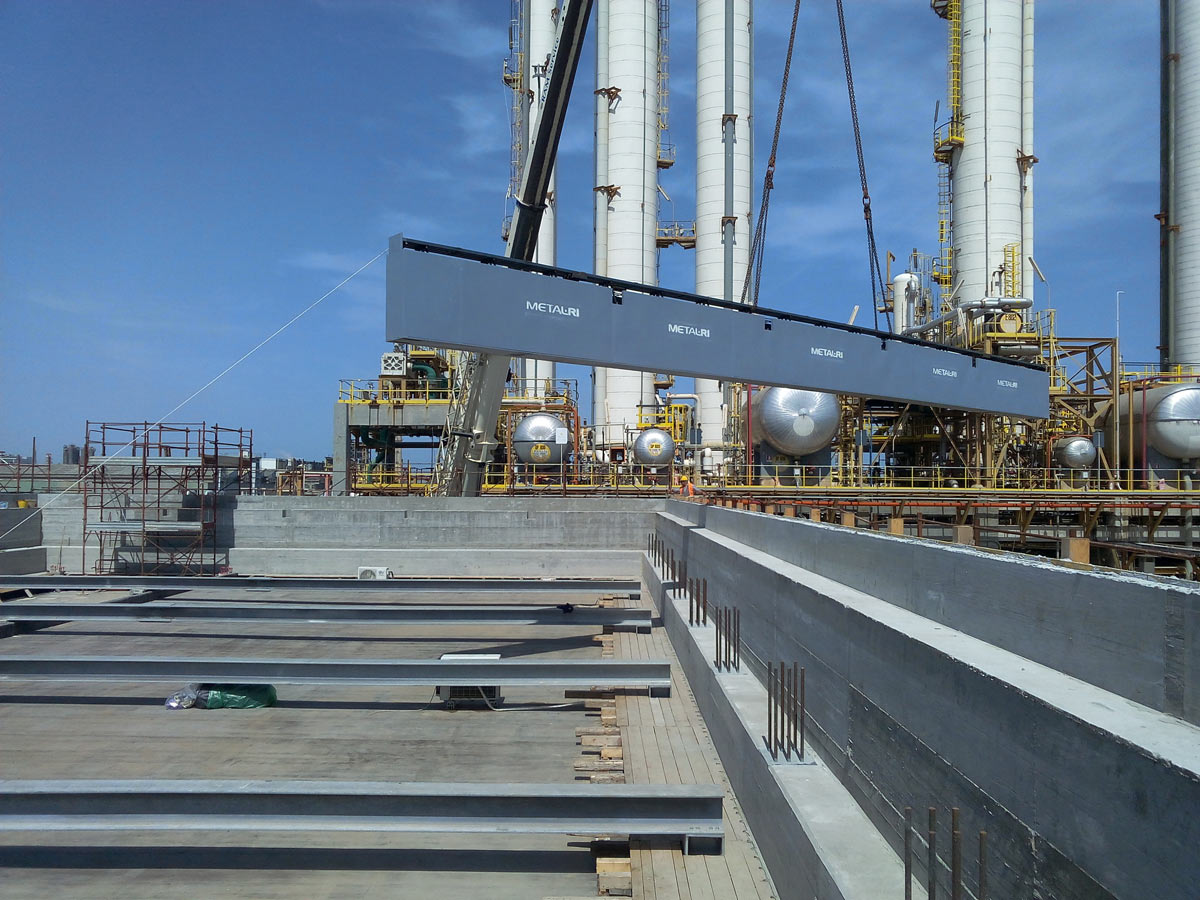
Self-supporting during deck assembly and casting, with steel bottom plate.
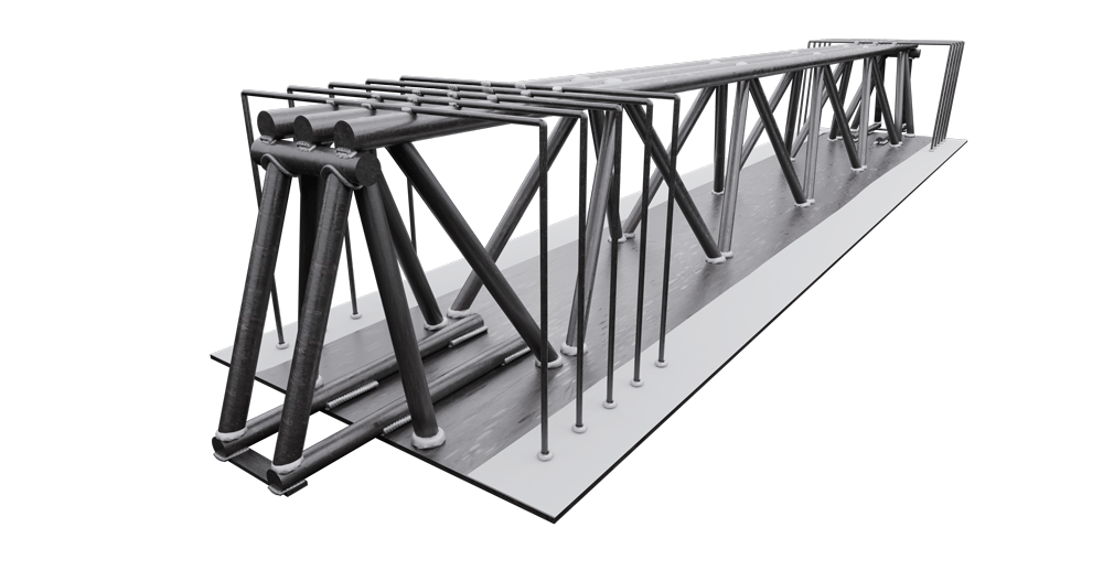
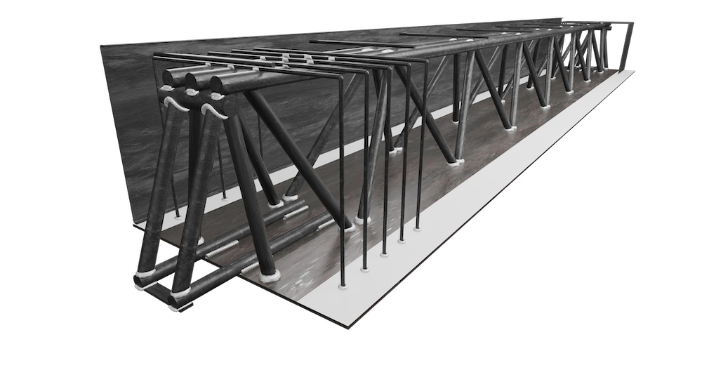
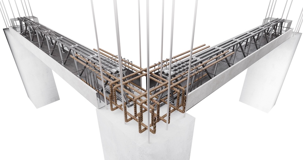
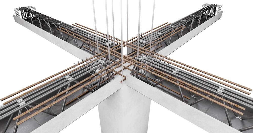
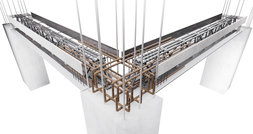
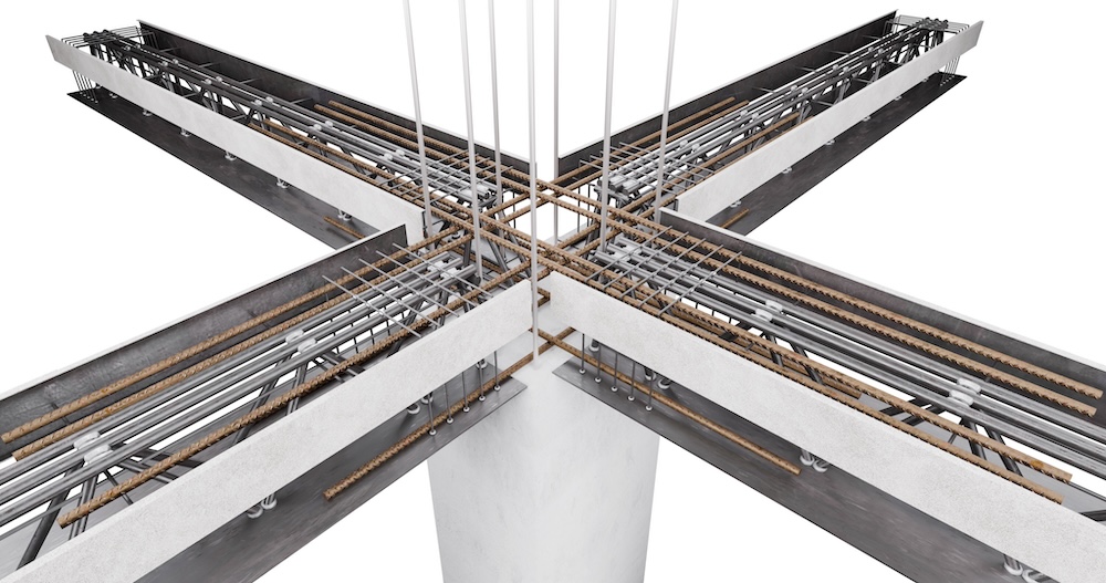
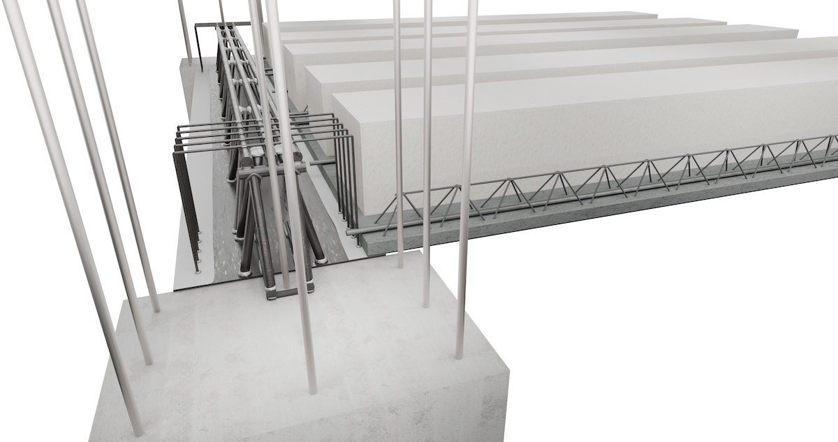
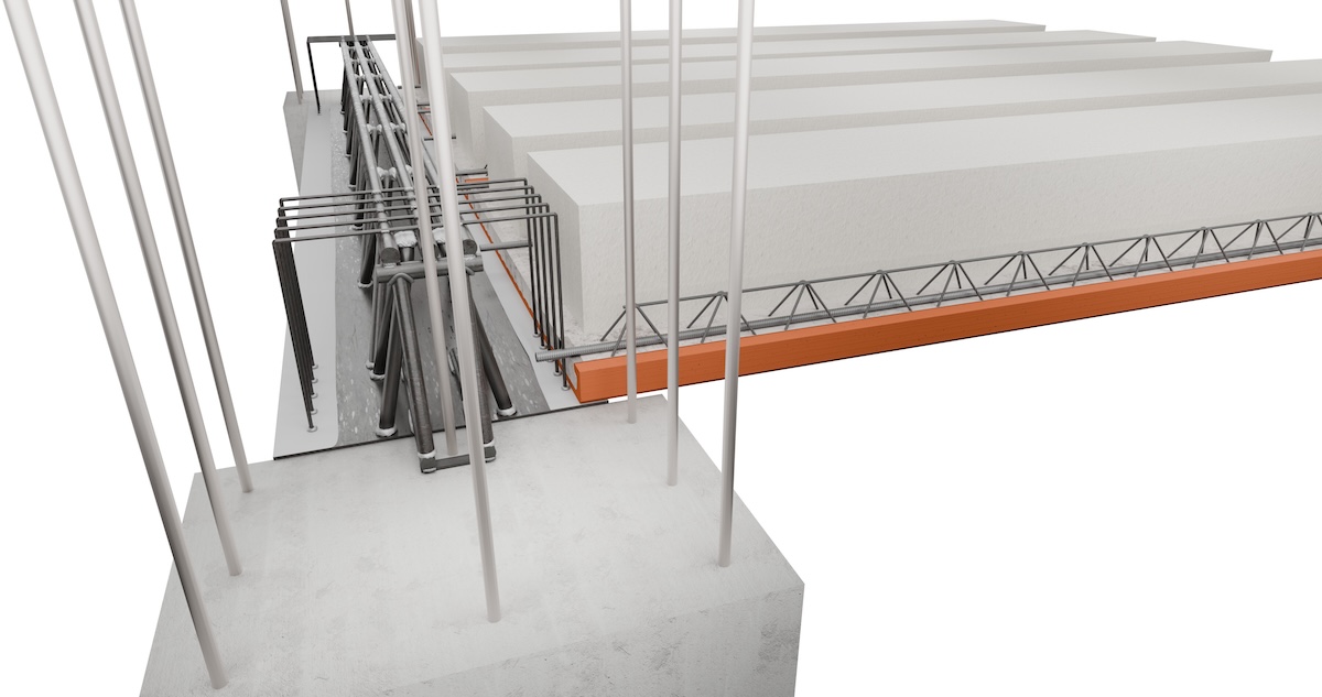
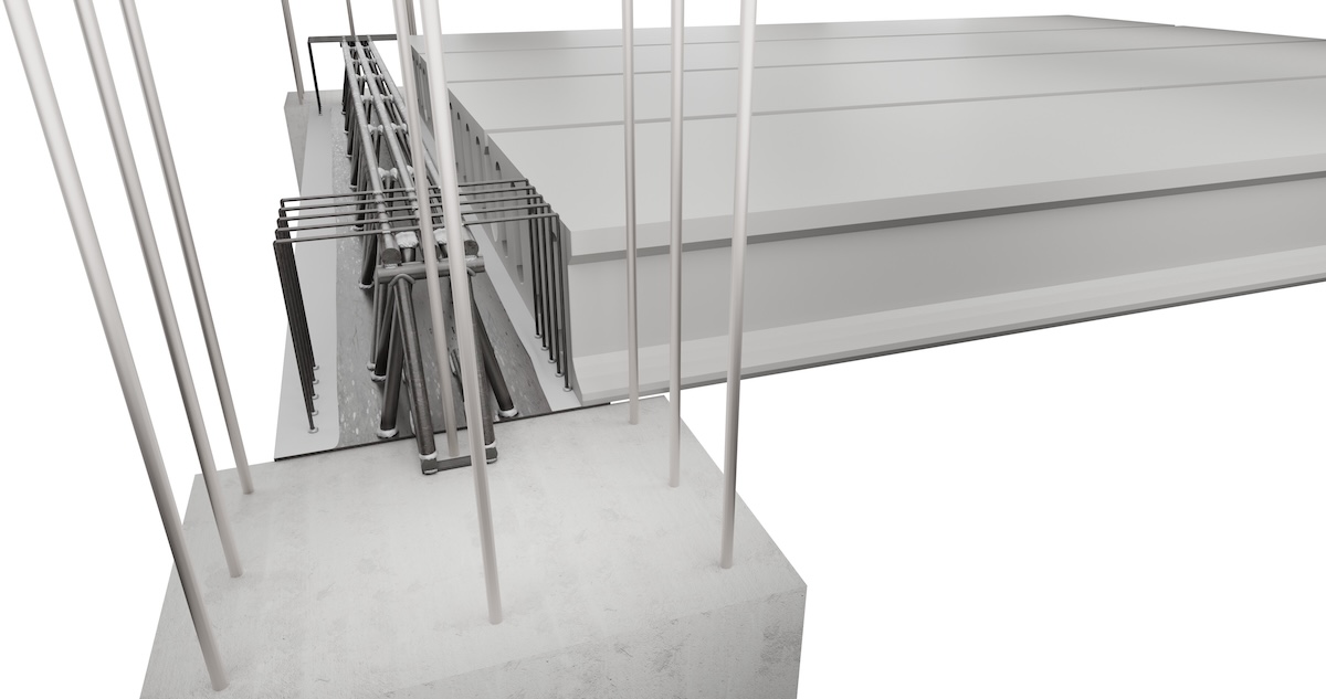
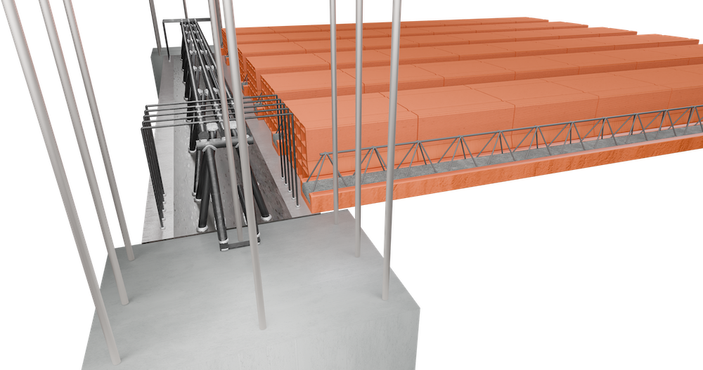
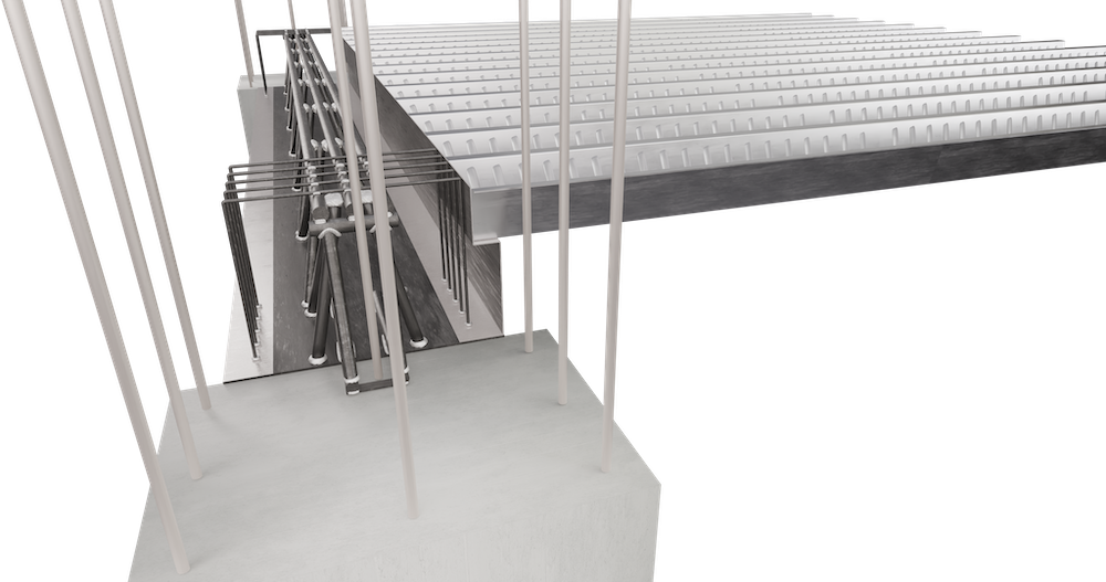
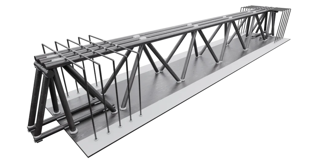
The MTR® A Beam, with its steel bottom plate, is self-supporting during both assembly and deck casting phase. It is designed to meet any architectural requirement and represents the ideal alternative to the construction limits that characterise traditional systems. The product has been CE marked in accordance with UNI EN 1090-1, and it is made up of a bottom steel plate, top chords, steel cores and steel reinforcement completed with cast-in-place concrete.
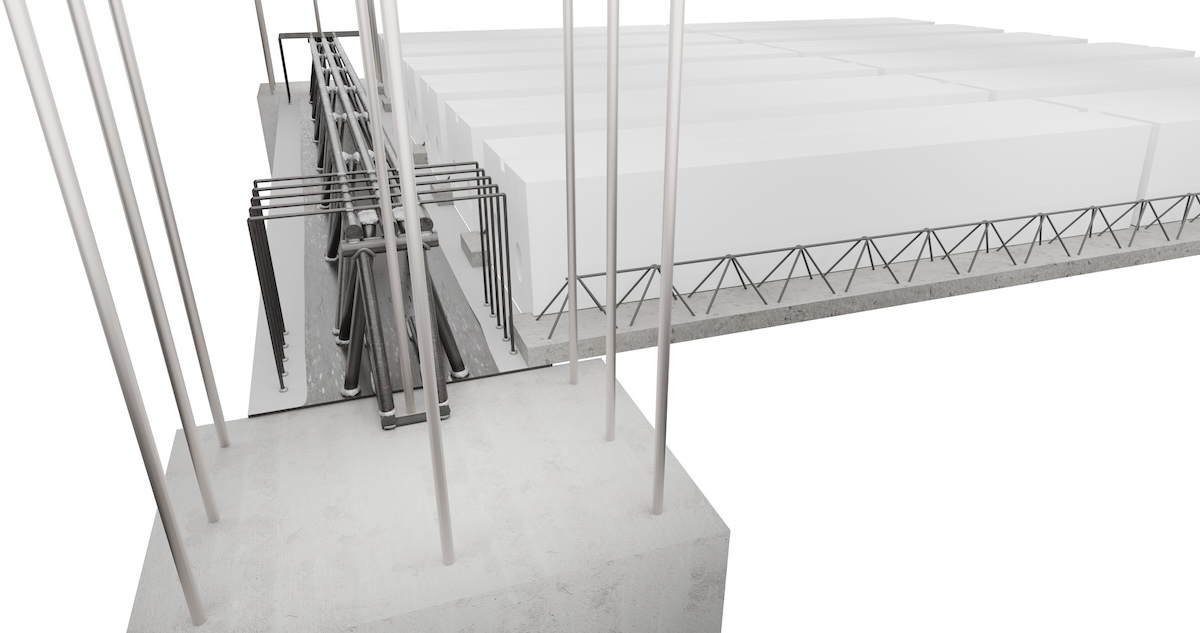
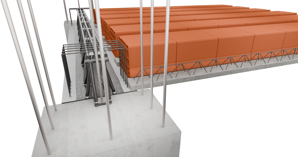
This structural solution allows the construction of framed structures in any seismic category, combined with different slab types depending on the building and the required performance.
Menu
MTR® A Beam
Characteristics of the MTR® A Beam
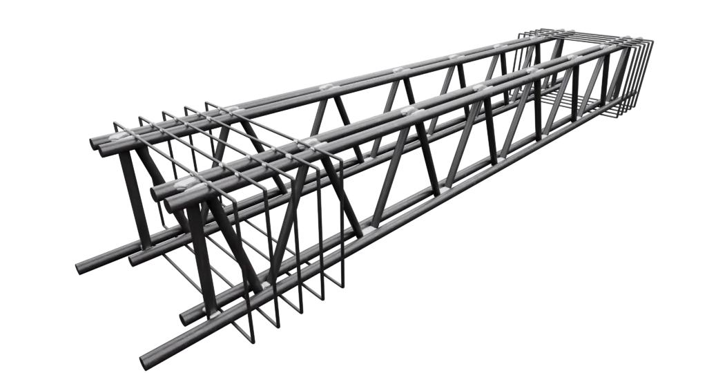
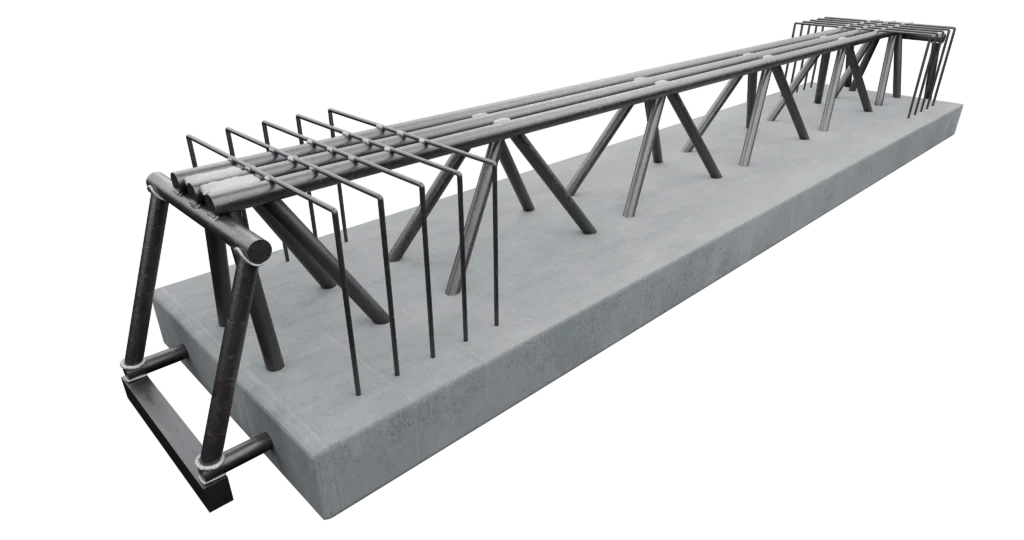
The structure consists of a bottom plate, top chords, and structural steel cores in accordance with EN ISO 10025-2, completed with cast-in-place concrete.
Cast-In-Place Concrete C25/30 unless otherwise specified by the structural designer.
Self-supporting capacity The beam supports itself and the slab burdening it from the very moment in which it is laid on the column, even before the completing casting.
Welding Continuous wire welding under shielding gas (Process EN ISO 4063-135) is carried out in compliance with NTC 2018.
Regulatory references Phase 1: Section 4.2 NTC 2018 and Eurocode 3. Phase 2: Sections 4.1, 4.2 and 4.3 NTC 2018 and Eurocodes 2, 3 and 4. Seismic design: Chapter 7 NTC 2018 and Eurocode 8.
Design The calculation procedure of the MTR® Software has been developed in accordance with the latest regulations.
Fire resistance (R) Native R 60/90/120 or achieved through the use of intumescent coatings, fire-resistant plasters, or REI plasterboard cladding.
Base Steel bottom plate in accordance with EN ISO 10025-2 with the function of reinforcement, support for the slab and formwork for the completing casting.
Product certification CE marked in accordance with EN 1090-1
Types
The MTR® A beam can be manufactured in different configurations to ensure maximum design flexibility:
Bottom Plate Treatments
This treatment is designed to protect the steel and create a surface that is ready for plastering. The same technique is used for non-structural steel sheets, which are used for edge and downstand beams.
The bottom base of the MTR® A beam is always treated with anti-rust primer on both sides and gripping resin for plaster only on the rough part to be plastered.® A è sempre trattato con primer antiruggine su entrambi i lati e resina aggrappante per intonaco solo per la parte a vista da intonacare.
Use of MTR® C beams – MTR® T beams with adequate concrete cover – MTR® A beams with native R 60/90/120 or treated with intumescent paints, fire-resistant plasters, or REI plasterboard cladding.
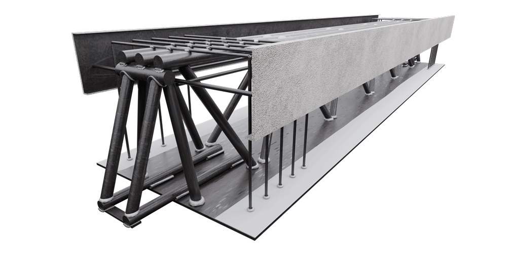
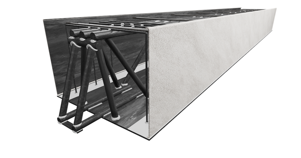
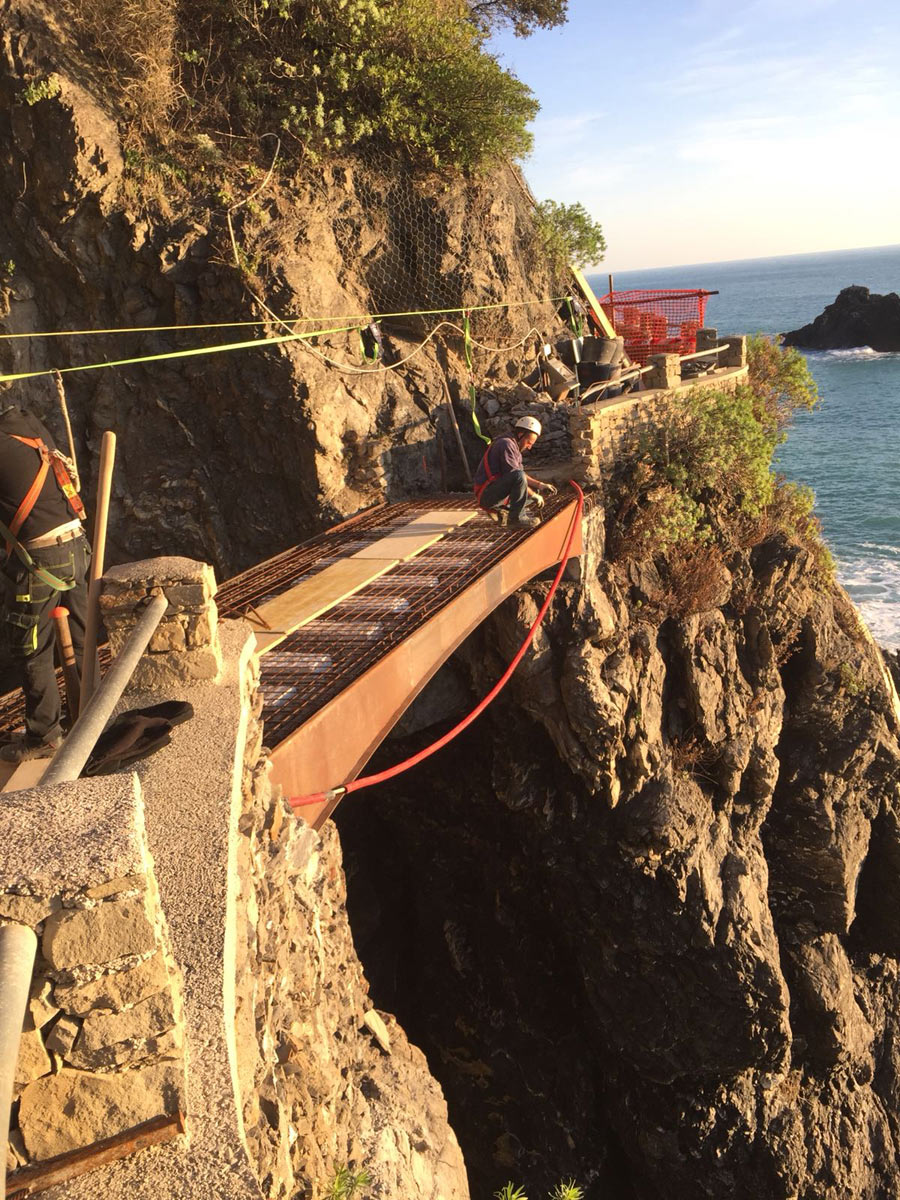
MTR® A beams are available upon request, complete with a corten steel bottom plate and lateral containment sheets.
In instances where painting is necessary, such as with predalles slabs or suspended ceilings, the treatment is restricted to anti-rust primer.
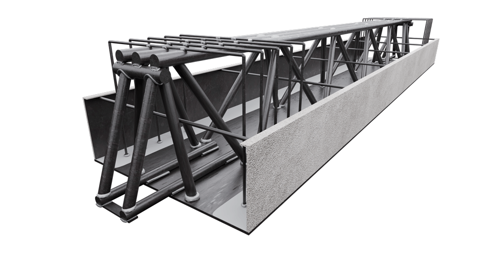
The MTR® A downstand MTR® A beam is subject to the same treatments as the slab-depth version: both the bottom plate and the side plates remain exposed and therefore require primer and, where applicable, gripping resin.® A a spessore: oltre al piatto, anche le sponde rimangono a vista e necessitano quindi di trattamento con primer ed eventuale resina aggrappante.
The MTR® A upstand MTR® A beam has the bottom plate treated as in the slab-depth configuration (primer only or primer + gripping agent), while the upper side plates typically receive only primer, as they will be protected by external waterproofing membranes upon completion.
Structural Joints
Support Systems and Structural Connections
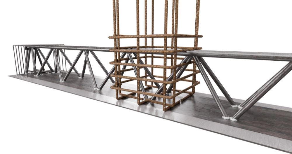
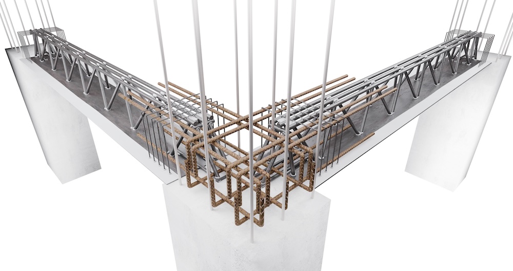
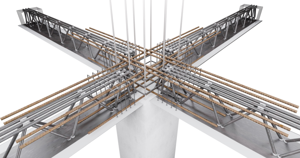
The MTR® System is supported by vertical load-bearing elements, including columns and shear walls, through custom-designed support systems that are welded to the beam ends. These are engineered to withstand Phase 1 loads and to avoid interference with starter bars. Connections between MTR® System elements and adjacent structural elements, such as continuous beams, columns and shear walls, are achieved through structural joints using B450C reinforcing steel.
Support on columns
The MTR® beams are supported on masonry or columns by dedicated end support systems.
Steel reinforcement
The MTR® beams are delivered to site complete with continuity reinforcement for joints, made of B450C reinforcing steel.